If you're a developer, whether starter or expert, or manage a fleet of vehicles, you understand the importance of consistent maintenance to ensure smooth operations. But, are you familiar with OBD2 and its functionality?
We specialize in leveraging OBD2 technology to help you keep your vehicles in top condition. Whether you're looking to enhance fuel efficiency or ensure compliance with emission standards, our comprehensive guide will walk you through everything you need to know about OBD2. For a quick overview, watch our 4 Minute OBD2 Tutorial.
What is OBD2?
In short, OBD2, or OBD-II, is a diagnostics system found in today's cars and trucks.
It's like the vehicle's health check mechanism, consistently monitoring different parts and systems. When its system detects a potential problem, a check light will pop up on your dashboard as an alert.
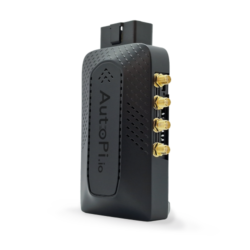
The AutoPi TMU device integrates seamlessly with your vehicle's OBD2 system to provide advanced diagnostics and real-time monitoring, ensuring optimal performance and early detection of potential issues.
The OBD2 system gathers crucial information from various sensors throughout the vehicle. The car's engine control unit (ECU), acting as the vehicle's brain, processes this information to pinpoint issues. This could range from problems with the engine, exhaust emissions, or even fuel efficiency.
For example, if you've ever noticed your fuel consumption becoming less efficient, the OBD2 might identify a faulty oxygen sensor as the culprit, signaling you to address the issue before it worsens.
This is the car's way of telling you, that there is a problem within its system, by showing you the malfunction indicator light on your dashboard.

How Does OBD2 Work?
OBD2 gathers information from sensors located in your car's engine and other systems.
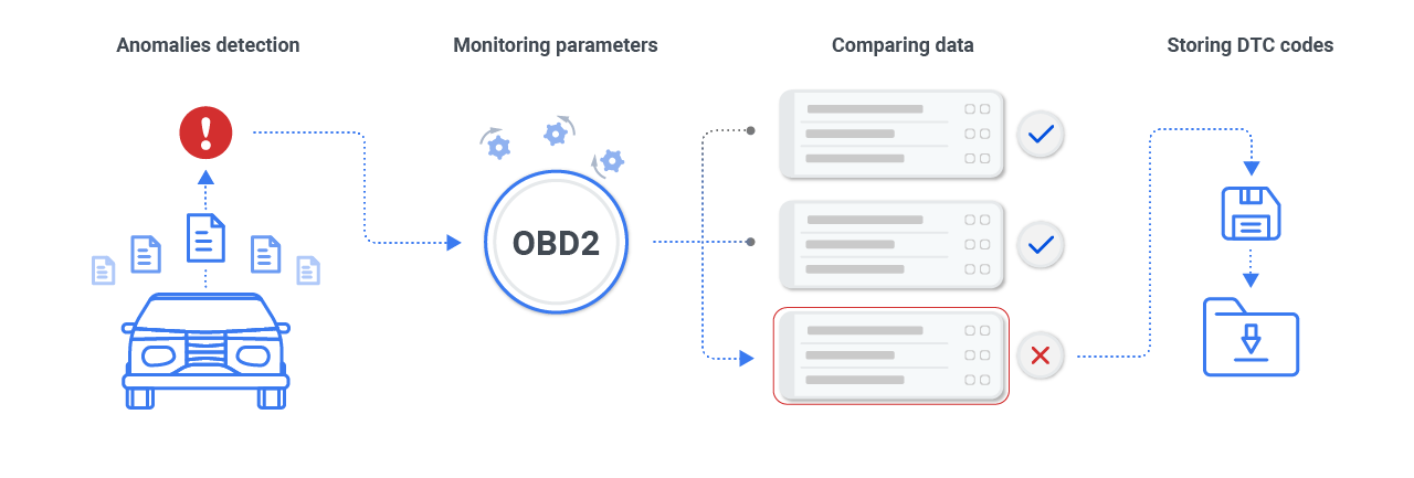
When it detects an issue, it produces diagnostics trouble codes (DTC). These codes can be read using a OBD2 scanner or an automotive data logger, helping you understand and fix any vehicle performance hitches.

You connect the telematics device to the OBD2 port, typically found under the car's dashboard, but can be found in other areas as well.
See where the OBD2 port is located.
This port has a standard design that lets the diagnostics device communicate with the car's main computer (CAN bus) and fetch the DTCs.
Is My Car OBD2 Compatible?
When it comes to determining if your vehicle is equipped with an OBD2 system, the key factors to consider are not where your car was manufactured or initially purchased. Instead, compatibility hinges on the model year and specific regulations applicable to the country where the vehicle was sold new. Below, we simplify the process of figuring out your car's OBD2 status, so you can easily understand what to look for.

If your car is newer than 1996 in the US, or 2001 in the EU, then your car is most likely OBD2 compatible.
Please note: This list serves as a simplified guide. Vehicle compatibility with OBD2 can be influenced by specific models or manufacturer practices. Always consult your vehicle's manual or contact the dealership for the most accurate information.
|
Country of Sale
|
Model Years Covered
|
Important Notes
|
|---|---|---|
| USA | 1996 and newer | All petrol-powered vehicles are OBD2 compliant from 1996 onwards. Diesel vehicles followed suit in 2004. |
| European Union | 2001 and newer (petrol) / 2004 and newer (diesel) | Includes member states as of the implementation dates. |
| Japan | 2002 and newer | JDM vehicles typically comply from 2002, but imported vehicles might differ; verify with the manufacturer. |
| Australia | 2006 and newer | Australian Design Rules (ADR) incorporate OBD2 compliance from 2006 for most passenger vehicles. |
| Canada | 1998 and newer | Canadian vehicles align closely with US standards, adopting OBD2 in 1998 for gasoline vehicles. |
OBD2 scanner
An OBD2 scanner is essential in order to diagnose and maintain vehicle health. It is a diagnostic tool that connects to a vehicle's OBD system to read and clear error codes, monitor vehicle performance, and provide data about various vehicle systems. Understanding how to connect and use an OBD2 scanner helps you interpret diagnostic trouble codes effectively, preventing major repairs and keeping your vehicle in optimal condition.
Go Beyond Error Codes with AutoPi
If you wanna really keep track of your car’s health, the AutoPi CAN FD Pro is definitely worth checking out.
It’s not just another OBD2 scanner—it actually hooks up to your car’s systems and gives you live updates on everything from fuel economy to how your engine’s doing. Whether you’ve got a fleet to manage, enjoy fixing up your own car, or you just want to know what’s going on under the hood, this thing helps you catch issues before they get out of hand and cost you a ton. The AutoPi CAN FD Pro plugs straight into your car’s CAN bus system and it’s super easy to install.

So instead of just getting a generic DTC error code, you get a full rundown of your car’s health and performance.
How Does OBD2 logs data?
The OBD2 system continuously monitors various parameters within the vehicle. As it collects data, it compares this information to pre-set standards.

If any discrepancies or anomalies are detected, the system flags these as potential issues, translating them into DTCs. These codes are then stored within the onboard computer, ready to be accessed by diagnostic tools.
Here's a guide to how to read obd2 codes
OBD2 and CAN bus Connection
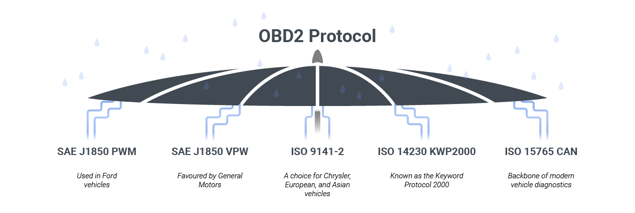
The OBD2 diagnostics act as a higher layer protocol, while the CAN serves as its communication method. The OBD2 standard defines a distinct connector, encompassing five main protocols.
Notably, since 1996, the CAN bus has been an essential OBD2 protocol for all vehicles in the U.S. By 2001, Europe mandated all cars to be OBD2 compliant, and this became a requirement in Australia and New Zealand starting 2006.
The five OBD2 signal protocols
Diving into the world of car diagnostics, think of the OBD2 system as the main artery of communication in your vehicle. But here’s the twist: not all cars speak the same language. Picture five dialects under the OBD2 umbrella, each with its own flair and rules. It's like choosing the right fuel for your ride; picking the correct OBD2 protocol is key for smooth chats between your car and the diagnostic gear, shining a light on the car's health.

Why so many, you ask? It’s a mix of history’s favorites and the needs of now, blending old-school cool with modern tech. Coming up, we’ve got a neat snapshot of these five communication styles. Our table’s packed with the need-to-knows — from pin setups to voltage vibes — making it easier for you to get the gist of your car's internal conversations and how it gets along with diagnostic tools.
SAE J1850 PWM
Primarily used in Ford vehicles, this protocol communicates at 41.6 kbps, using Pulse Width Modulation to ensure reliable data transmission between the vehicle's systems and diagnostic tools.
|
Feature
|
Description
|
|---|---|
| SAE J1850 PWM (Ford) | Bus +: Pin 2, Bus -: Pin 10, 12V: Pin 16, GND: Pins 4, 5, State: Active when BUS + HIGH, BUS - LOW, Voltage: Max 5V, Min 0V, Bytes: 12, Bit Timing: '1' bit - 8uS, '0' bit - 16uS, Start of Frame - 48uS |
SAE J1850 VPW
Favored by General Motors, it operates at speeds of 10.4/31.6 kbps with a Variable Pulse Width, offering a unique method for data exchange that enhances diagnostic efficiency.
|
Feature
|
Description
|
|---|---|
| SAE J1850 VPW (GM) | Bus +: Pin 2, 12V: Pin 16, GND: Pins 4, 5, State: Idles low, Voltage: Max +7V, Decision +3.5V, Min 0V, Bytes: 12, Bit Timing: '1' bit - HIGH 64uS, '0' bit - HIGH 128uS, Start of Frame - HIGH 200uS |
ISO 9141-2
A choice for Chrysler, European, and Asian vehicles, this protocol facilitates asynchronous serial communication at 10.4 kbps, similar to RS-232, but with automotive-specific signal levels for broad compatibility.
|
Feature
|
Description
|
|---|---|
| ISO 9141-2 (Chrysler, Euro, Asian) | K Line: Pin 7, L Line (optional): Pin 15, 12V: Pin 16, GND: Pins 4, 5, State: K Line idles HIGH, active when LOW, Voltage: Max +12V, Min 0V, Bytes: Message 260, Data 255, Bit Timing: UART 10400bps, 8-N-1 |
ISO 14230 KWP2000
Also known as the Keyword Protocol 2000, it extends the capabilities of ISO 9141-2 by offering speeds up to 10.4 kbps and supports a wide range of vehicle diagnostic operations, especially in Chrysler, European, and Asian models.
|
Feature
|
Description
|
|---|---|
| ISO 14230 KWP2000 (Chrysler, Euro, Asian) | K Line: Pin 7, L Line (optional): Pin 15, 12V: Pin 16, GND: Pins 4, 5, State: Active when LOW, Voltage: Max +12V, Min 0V, Bytes: Data 255, Bit Timing: UART 10400bps, 8-N-1 |
ISO 15765 CAN
The backbone of modern vehicle diagnostics, this protocol is mandatory for all vehicles sold in the US from 2008 onwards. Operating at 250 kbit/s or 500 kbit/s, it leverages the CAN bus system for high-speed, robust data communication across the vehicle's network.
|
Feature
|
Description
|
|---|---|
| ISO 15765 CAN (US 2008+, Euro 2003+) | CAN HIGH (H): Pin 6, CAN LOW (L): Pin 14, 12V: Pin 16, GND: Pins 4, 5, State: Active CANH HIGH, CANL LOW, Idle floating, Voltage: CANH Max +4.5V, Min +2.75V; CANL Max +2.25V, Min +0.5V, Bit Timing: 250kbit/sec or 500kbit/sec |
Timeline OBD2

OBD 1 vs OBD 2
On-Board Diagnostics (OBD) systems, developed in the 1960s, have evolved significantly, with OBD1 in the early 1990s offering basic, manufacturer-specific diagnostics for emissions control, and OBD2, mandated since 1996, providing a standardized, comprehensive system that monitors a wide range of vehicle functions.
OBD2 enhances compatibility across manufacturers, tracks various sensor data, stores fault codes for intermittent issues, and facilitates precise real-time troubleshooting. The advantages of OBD systems include enhanced fuel efficiency, early malfunction detection, cost savings through proactive maintenance, emission control compliance, and improved vehicle safety. This technology continues to advance, integrating more sophisticated features for better vehicle diagnostics.
Maximize Your Vehicle Performance
Understanding and utilizing OBD2 technology is crucial for maintaining vehicle health, whether you are a developer, fleet manager, or vehicle owner. OBD2 systems provide comprehensive diagnostics, monitoring a wide range of vehicle functions and offering early detection of potential issues. By leveraging OBD2, you can enhance fuel efficiency, ensure compliance with emission standards, and maintain overall vehicle safety. With tools like OBD2 scanners and vehicle telematics devices, diagnosing and addressing vehicle performance issues becomes more efficient and effective, ultimately leading to significant cost savings and extended vehicle lifespan. Embrace OBD2 technology to keep your vehicles running smoothly and reliably.
Take Action Now
Explore our range of OBD2 tools and resources to keep your vehicles in top condition. Learn more about our devices, watch our 4-minute OBD2 tutorial, and start leveraging the power of OBD2 technology today!


