





















 Cloud Login

Need a simple, practical intro to CAN bus sniffing?
A CAN bus sniffer is used to monitor traffic on a vehicle CAN network. It helps engineers and technicians see which ECUs are communicating, what messages are present and how the vehicle behaves when different functions are used. The important part is to work on vehicles and systems you are allowed to test, and to keep safety-critical functions out of scope unless the work is done in a controlled engineering setup.
Modern cars are controlled by several Electronic Control Units (ECUs).
You can think of these as small embedded computers that control different electrical and mechanical functions in the vehicle.
The engine, brakes, transmission, body control, lighting, doors, climate system and infotainment can all have their own controllers.
These controllers communicate over vehicle networks such as CAN bus.
A CAN sniffer lets you listen to this communication.
It can be used for diagnostics, development, signal discovery, data logging and troubleshooting.
By connecting a telematics device like the AutoPi TMU CM4 or AutoPi CAN FD Pro, you can capture CAN traffic and work with it in a more structured way.
The goal is not to blindly send commands to a vehicle.
The goal is to understand the traffic, document the signals and use the data for a controlled diagnostic or engineering purpose.
A CAN frame can look like this:

In a CAN message, the identifier tells you which message is on the bus.
The payload contains the actual data bytes.
Without a DBC file, documentation or reverse engineering work, the payload is only raw bytes.
With the right context, those bytes can become useful values such as speed, RPM, voltage, temperature, switch state or diagnostic status.
Gaining access to the CAN bus allows you to observe how the vehicle communicates.
In authorized engineering work, you may also test message replay or transmission in a controlled environment.
This must be done carefully, because injecting messages into a vehicle network can affect real vehicle functions.
For normal diagnostics and data logging, passive monitoring is the safer starting point.
How to use a CAN bus sniffer in a controlled test setup
CAN bus sniffing is often used to discover which messages change when a vehicle function is used.
For example, you may monitor the bus while pressing a button, changing a setting, turning on lights or operating a switch in a test vehicle.
The captured data can then be compared before, during and after the action.
This helps identify which CAN IDs and payload bytes are related to the function.
This work should only be done on vehicles or systems where you have permission to test.
It should not be used to bypass access control, disable safety systems or interact with vehicles you do not own or manage.
A practical 5-step method for CAN bus signal discovery
- Identify the relevant CAN bus: Use the CAN sniffer to detect active vehicle buses and confirm bitrate, bus load and signal activity.
- Configure the vehicle profile: Add the relevant CAN bus to the device or cloud configuration, so recordings are made from the right interface.
- Record while performing the test action: Capture CAN messages while a known function is used in the vehicle. Repeat the action several times so the change is easier to find.
- Compare the recordings: Look for CAN IDs and payload bytes that change consistently when the action happens.
- Document the result: Save the suspected signal, test it carefully in a safe setup and document the CAN ID, byte position, scaling and expected behaviour.
This method is useful for signal discovery.
It does not replace OEM documentation, DBC files or proper validation.
The more important the function is, the more careful the validation should be.
What is CAN bus sniffer software?
CAN bus sniffer software is software used to monitor, capture and inspect messages on a CAN bus.
It is commonly used in automotive, industrial, marine, agriculture and embedded systems.
The software normally works together with CAN hardware.
The hardware connects to the CAN network.
The software displays the traffic in a readable format.
This can be raw hexadecimal frames, decoded values from a DBC file, timestamps, counters or filtered message views.
CAN sniffer software is useful for:
- Diagnostics: Check whether expected messages are present on the bus.
- Signal discovery: Find which CAN IDs and payload bytes change when a known function is used.
- Data logging: Record traffic over time for later analysis.
- Development: Validate ECU communication, gateways and embedded software.
- Fleet and machine monitoring: Collect selected CAN data and send it to dashboards or backend systems.
The key point is context.
Raw CAN data is useful only when you know what it means or when you have a method to discover it safely.
How a CAN bus sniffing tool works
A CAN bus sniffing tool connects to the CAN network and listens to the traffic.
Depending on the hardware and setup, it can work through the OBD-II port, a direct CAN connection, a diagnostic connector or a test harness.
- Connection: The tool connects to the vehicle CAN network through a supported connector or interface.
- Monitoring: It listens to the CAN traffic and captures frames with timestamps, IDs and payloads.
- Filtering: The user can filter by CAN ID, bus, time range or payload pattern to reduce noise.
- Decoding: If DBC files or signal definitions are available, the raw frames can be converted into readable values.
- Analysis: The captured data can be used to diagnose problems, validate behaviour or build data pipelines.
Advanced testing can include transmitting messages on a test bench or controlled vehicle setup.
This should be done with care and only where it is allowed.
A wrong message, wrong bitrate or wrong timing can create unexpected behaviour on the vehicle network.
To take full advantage of CAN bus data, the AutoPi CAN FD Pro can be used for professional CAN, CAN FD, LIN, OBD2 and J1939 logging projects.

How to use a CAN bus sniffing tool
Finding one useful signal inside a large CAN log can be difficult.
A common method is to record a known action, then compare the messages that changed during that action.
The “divide and conquer” idea can help when the log is large.
Instead of reading thousands of lines manually, you reduce the dataset step by step until the likely messages are easier to inspect.
A controlled signal-discovery process can look like this:
- Record a baseline: Capture CAN traffic while the vehicle is idle and the function is not being used.
- Record the action: Capture CAN traffic while the known test action is performed several times.
- Compare the captures: Look for CAN IDs that change only when the action happens.
- Reduce the candidates: Filter out messages that are periodic, unrelated or changing all the time.
- Validate the signal: Confirm that the candidate signal behaves consistently across repeated tests.
- Document the signal: Add the message ID, byte position, bit length, scaling, unit and notes to your project documentation or DBC file.
Below is a sample from a CAN log recorded over a short period:

The AutoPi system helps simplify this process by giving you a structured interface for CAN recording, filtering and device management.
It can be used as a CAN bus sniffer for diagnostics, development and data logging projects.
The rewards of reverse engineering your CAN bus
Reverse engineering CAN bus data can be useful when official documentation or DBC files are not available.
The goal is to understand the vehicle communication well enough to use the data safely and correctly.
This can help in diagnostics, integration, machine monitoring and engineering validation.
Typical benefits include:
- Better system understanding: See how ECUs and controllers communicate during real operation.
- More precise diagnostics: Use bus traffic to support fault finding and troubleshooting.
- Useful customization: Build dashboards, alerts and integrations based on real vehicle data.
- Security awareness: Understand how exposed vehicle networks behave and where access should be controlled.
- Development insight: Validate embedded systems, gateways and vehicle software during testing.
- Lower tool dependency: Use open logs and decoded data instead of relying only on closed tools.
- Practical learning: Learn CAN, embedded systems and vehicle networks using real traffic.
CAN bus reverse engineering can give very useful insight, but it should be handled responsibly.
Keep testing authorized, document what you find and avoid interacting with safety-critical systems unless you have the right environment and process.
Unlocking vehicle data with AutoPi
The AutoPi device, together with AutoPi Cloud, makes CAN traffic easier to capture, organize and work with.
Instead of manually handling all recordings on a laptop, the workflow can be moved into a managed device and cloud setup.
This is useful for fleets, prototype testing, vehicle data projects and customer integrations.
A typical AutoPi workflow looks like this:
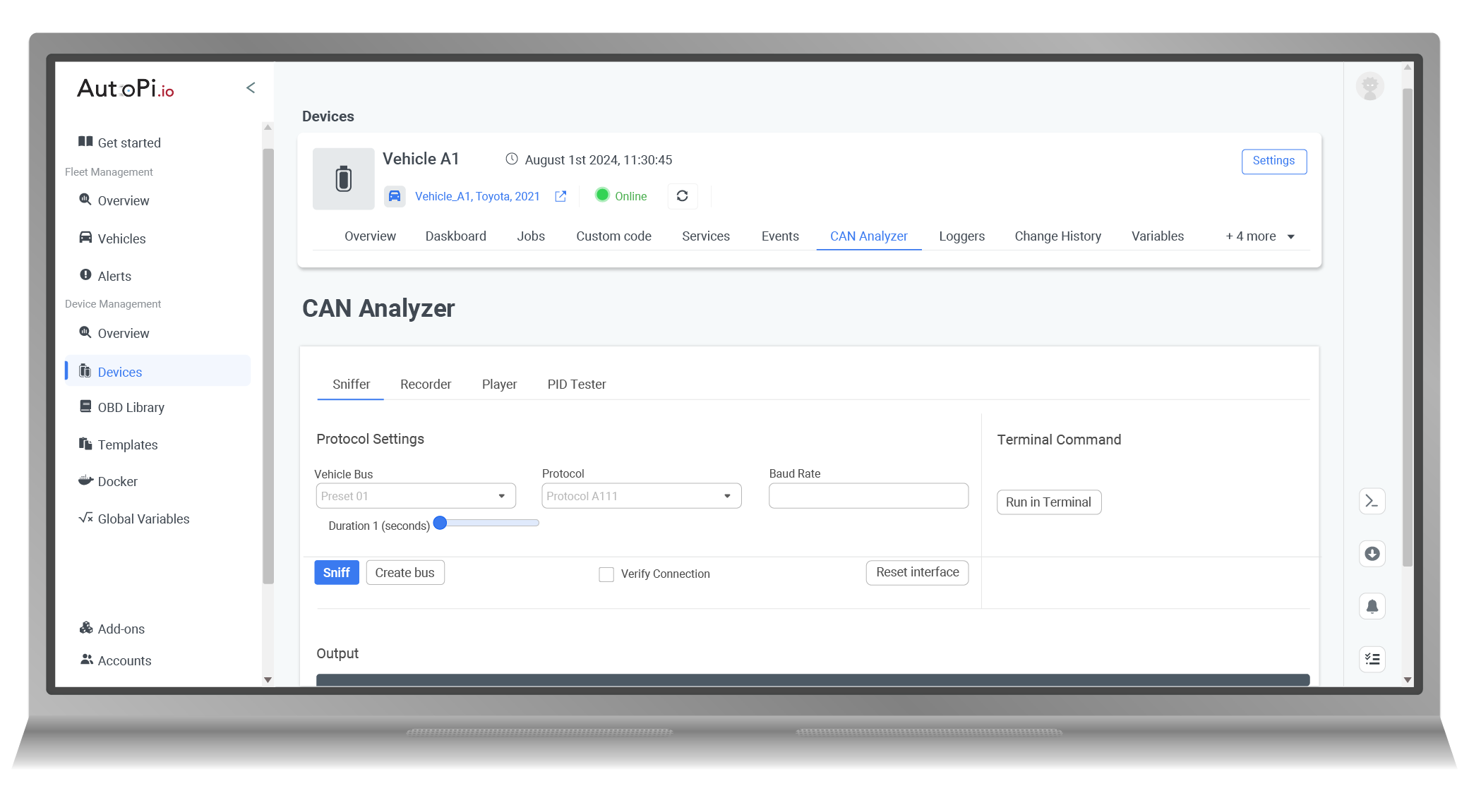
- Connect with CAN Explorer: Open the CAN Explorer or relevant device tool and connect to the vehicle bus.
- Start recording: Record CAN traffic while the vehicle is in the state or operating condition you want to analyze.
- Stop and analyze: Stop the recording and review the captured traffic, filters and candidate messages.
- Save useful definitions: Save confirmed signals, commands or observations in the platform or project documentation.
Decoding raw CAN messages can be difficult, especially when you are new to vehicle networks.
That is why a structured logging flow is important.
You can also read the guide on how to log raw CAN messages.
After a signal or command is confirmed, it can be used in the project where it makes sense.
For example in a dashboard, alert, data pipeline or controlled test workflow.


